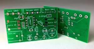
Understanding how to read a circuit board diagram is crucial for anyone involved in electronics, whether you’re a seasoned engineer or a hobbyist looking to tinker with electronic devices. A circuit board diagram, also known as a schematic diagram, is a detailed map of an electronic circuit that guides users in assembling or troubleshooting circuit boards.
In this article, we will break down the process of reading a circuit board diagram in easy-to-understand English, making it accessible even for beginners. You may also like Top 10 Universities in World For Computer Science
Introduction to Circuit Board Diagram
A circuit board diagram is a graphical representation of the components and connections within an electronic circuit. It consists of symbols representing different components like resistors, capacitors, and transistors, connected by lines to indicate electrical connections. Learning to understand these symbols and connections is essential to accurately interpreting the diagram.
Importance of Reading Circuit Board Diagrams
Being able to read circuit board diagrams is integral for anyone looking to build, repair, or modify electronic devices. It allows users to:
- Identify components and their relationships within a circuit.
- Understand the flow of current within the circuit.
- Diagnose and troubleshoot problems in a malfunctioning circuit.
Understanding the Basic Symbols
Before diving into the intricate details of a circuit board diagram, it’s important to familiarize oneself with the basic symbols used to represent common electronic components.
Resistors
Resistors are depicted by a zigzag line. They restrict the flow of current within a circuit and are used to protect components from excessive current.
Capacitors
Capacitors are represented by two parallel lines. They store and release electrical energy and are often used to stabilize voltage and power supply.
Transistors
Transistors are symbolized by a combination of arrows and lines. They act as amplifiers, switches, or signal modulators within the circuit.
Diodes
Diodes are illustrated by a triangle pointing to a line. They allow current to flow in one direction only, providing controlled directionality within the circuit.

Analyzing Circuit Board Diagram Layout
A circuit board diagram typically presents a logical layout, not a literal representation of how components are arranged on the actual circuit board. The diagram emphasizes the electrical connections between components, not their physical locations.
Components and their Values
Every component within a circuit board diagram is labeled with a unique identifier and its value. For example, resistors may be labeled as R1, R2, R3, etc., with values in ohms. Capacitors might be marked as C1, C2, C3, etc., with values in farads.
Connection Lines
Lines in a circuit board diagram represent electrical connections. A line between two component symbols means they are electrically connected. A ‘dot’ at the intersection of two lines denotes a connection, while ‘jump’ symbols indicate that the lines cross each other without connecting.
Interpreting Connection and Flow
Once familiar with the symbols and layout of a circuit board diagram, understanding the connections and the flow of current between components is the next step. Follow the lines connecting the symbols to see how the components interact and how the current flows through the circuit.
Series and Parallel Connections
Components connected in series have a single path for current to flow, while components in parallel have multiple paths. Identifying these connections is crucial to understand the overall behavior of the circuit.
Voltage and Current Flow
The voltage sources in a circuit board diagram dictate the flow of current within the circuit. Understanding the voltage levels at different points in the circuit helps in analyzing the functioning of the entire circuit.
Detailed Component Analysis
A circuit board diagram often involves various components, each contributing to the overall functionality of the circuit. Understanding the role of each component is crucial.
Integrated Circuits (ICs)
ICs are depicted as rectangles with multiple connection points. They are assemblies of multiple electronic components packaged together to perform specific functions within the circuit.
Oscillators and Clocks
Oscillators and clocks generate periodic signals to control the timing of the circuit’s operation. They are crucial for circuits requiring precise timing, like microcontrollers and CPUs.
Filters and Amplifiers
Filters are used to allow certain frequencies to pass through and block others, while amplifiers increase the amplitude of signals. Both are significant in shaping the signal within the circuit.

Troubleshooting Using Circuit Board Diagram
A comprehensive understanding of a circuit board diagram is essential for effective troubleshooting. Identifying and resolving issues within the circuit requires a methodical approach.
Continuity and Short Circuits
Using the diagram, one can check for continuity between different points in the circuit to ensure proper connections. Identifying unintended connections or short circuits is also crucial in troubleshooting malfunctioning circuits.
Component Failure Analysis
By closely analyzing the circuit board diagram, one can isolate individual components and test them for failures. Replacing defective components is often necessary to restore the circuit’s functionality.
Signal Analysis
Understanding the expected signal at various points in the circuit helps in identifying abnormalities and resolving issues related to signal integrity.
Conclusion
Learning to read a circuit board diagram is akin to learning a new language. It requires familiarizing oneself with the symbols, understanding the layout, analyzing connections, and interpreting the flow of current and signals within the circuit. With patience and practice, anyone can master the skill of reading a circuit board diagram, opening the doors to the fascinating world of electronics.
Whether you’re an aspiring engineer, an enthusiastic hobbyist, or a professional looking to refine your skills, acquiring the ability to interpret a circuit board diagram is invaluable. It not only empowers you to create and modify electronic devices but also enables you to diagnose and fix issues, making it a quintessential skill in the field of electronics.
This article has provided a foundational understanding of how to read a circuit board diagram. However, delving deeper into each component, practicing with real-world diagrams, and applying the knowledge practically will help in gaining proficiency in this essential skill.


